EXPLANATION OF REVERSE ENGINEERING THROUGH 3D CAD SOFTWARE - INDIVIDUAL STEPS
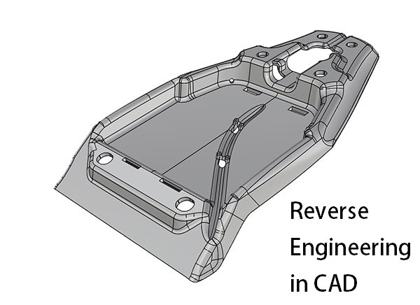
Manual Reverse Engineering in CAD.
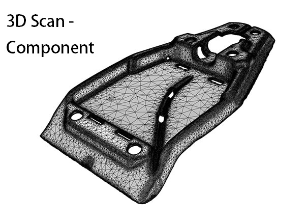
Optimal CNC data are reconstructed from the component using a 3D Scan.
REVERSE ENGINEERING WITH CAD SOFTWARE
Reverse Engineering is the manual reconstruction of a point cloud in CAD
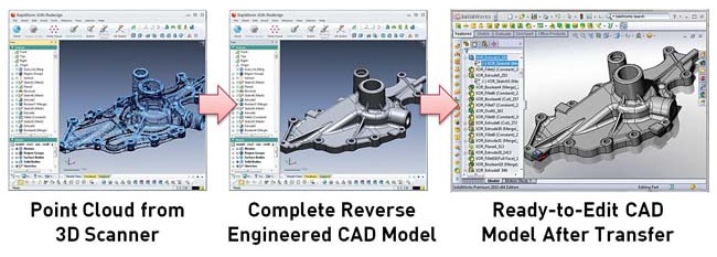
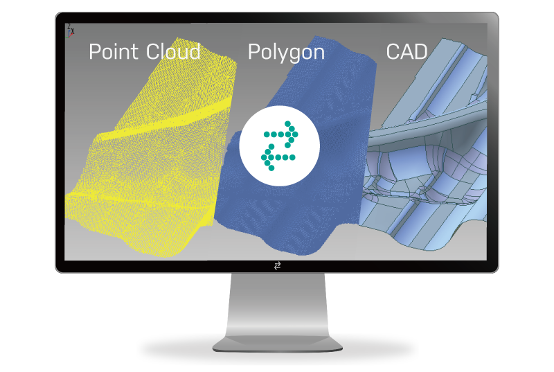
A point cloud is imported into the CAD software. Reverse engineering then replaces the points of the STL network with areas of the same size. Deviations and damage are removed from the scan.
Explanation of reverse engineering using the following example:
The imported mesh of a machine component contains an area that contains a flat and rectangular area with the dimensions 85 x 150 mm. This area is represented in the point cloud by approx. 3000 points. In the cross-section you can also see that these points are not on the same plane, but rather deviate by 0.05 mm upwards / downwards. These 3000 points were generated by the scanner. The deviation of 0.05 mm is the tolerance of modern 3D scanners. The designer now creates a rectangle with a size of 85 x 150 mm, replacing the area of 3000 points.
When all points have been replaced with new, reconstructed surfaces, this data record can be saved as a surface or volume model in STEP, or as native data, in the data format of the CAD software.
The advantages of this CAD data are as follows:
1. Reverse engineering removes scan deviations.
2. Reverse engineering reduces the amount of data considerably.
3. Reverse engineering creates surface or volume models that can be further processed in CAD.
There are other advantages such as - The removal of damage, optimization of the surfaces (automotive). We are at your disposal for a free telephone consultation without obligation. You can reach us from Monday to Friday between 9 a.m. and 6 p.m. on the phone number +49 2834 4629 681, or by email at mk@mako-technics.com
3D REVERSE ENGINEERING SERVICES FOR CAD
Reverse-Engineering in Parametric Data
Create CAD Data with Parametric History
For reading data directly, we offer parametric data records. We offer native CAD Data in:
- Reverse Engineering in Solidworks
- Reverse Engineering in Autodesk
- Reverse Engineering in Inventor
- Reverse Engineering in CREO
- Reverse Engineering in Catia
CAD Data for these Softwares are always created with parametric history. To change single geometric elements of the scanned object, we create a CAD file according to your demand in the data format you need.
For example Solidworks - The geometry of the scan-data is directly recreated in Solidworks. The result is a Solidworks file, which can be opened and edited with parametric History in Solidworks.
1. SolidWorks Reverse Engineering Services – Native SolidWorks Models with Construction History
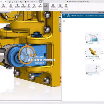
Our SolidWorks reverse engineering services convert 3D scan data, mesh files (STL, OBJ), point clouds, and physical components into fully editable native SolidWorks CAD models with complete construction history. Every model is created using parametric features, sketches, and design intent, allowing engineers to modify dimensions, update features, and make design improvements without recreating the model. Whether you need legacy part conversion, product redesign, or manufacturing-ready CAD data, our SolidWorks reverse engineering solutions deliver precision, flexibility, and long-term usability.
Key Benefits
- Native SolidWorks (.SLDPRT & .SLDASM) files
- Complete feature tree and construction history
- Fully parametric and editable CAD models
- Accurate 3D scan to CAD conversion
- Ideal for product redesign, manufacturing, and quality inspection
- Supports legacy part digitization and engineering modifications
2. Autodesk Reverse Engineering Services – Native Autodesk Models with Construction History
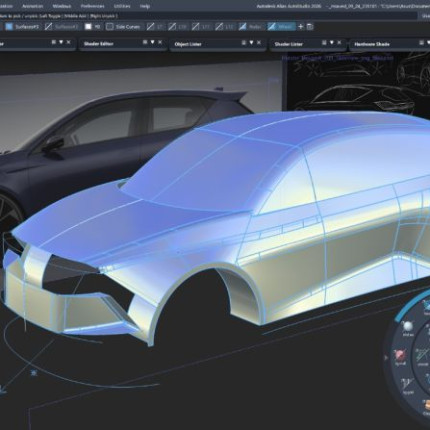
Our Autodesk reverse engineering services provide highly accurate native Autodesk CAD models with complete construction history for seamless editing and future design updates. Using advanced CAD reconstruction techniques, we convert scanned data, mesh models, and existing components into fully parametric models that preserve the original design intent. The resulting Autodesk files integrate smoothly into engineering, simulation, manufacturing, and product development workflows.
Key Benefits
- Native Autodesk CAD files with editable feature history
- Parametric CAD models for easy design modifications
- Precision reverse engineering from scan data and meshes
- Supports manufacturing, simulation, and documentation
- Faster product development and engineering change management
- Preserves design intent for future revisions
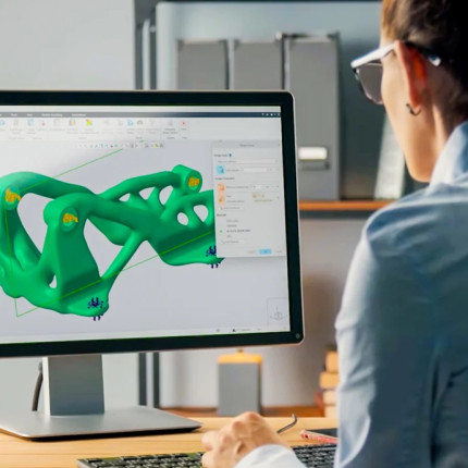
3. Creo Reverse Engineering Services – Native Creo Models with Construction History
Our Creo reverse engineering services transform 3D scan data, mesh files, and legacy parts into fully editable native Creo CAD models with complete construction history. Each model is built using intelligent parametric features, enabling engineers to modify geometry, update dimensions, and optimize product designs without rebuilding the CAD model. Our Creo reverse engineering solutions help manufacturers reduce design time while maintaining exceptional accuracy and engineering integrity.
Key Benefits
- Native Creo parametric CAD models
- Complete feature tree and construction history
- High-accuracy scan-to-CAD conversion
- Editable sketches, features, and dimensions
- Simplifies redesign and product optimization
- Manufacturing-ready CAD data for engineering workflows
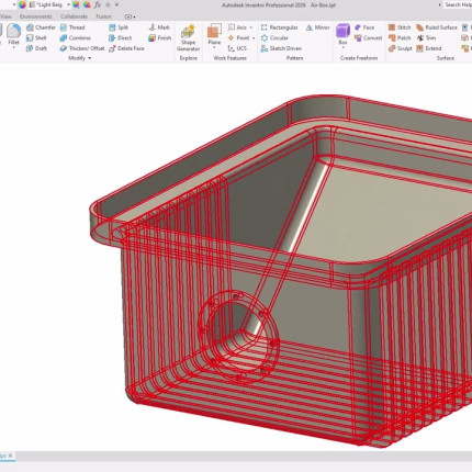
4. Autodesk Inventor Reverse Engineering Services – Native Inventor Models with Construction History
Our Autodesk Inventor reverse engineering services create fully editable native Inventor CAD models with complete construction history from 3D scans, mesh files, or physical parts. Every model is developed using intelligent parametric features that preserve design intent and allow quick engineering modifications. Whether you're replacing legacy drawings, improving existing products, or preparing designs for manufacturing, our Inventor reverse engineering solutions provide accurate, feature-based CAD models ready for production.
Key Benefits
- Native Autodesk Inventor (.IPT & .IAM) files
- Fully editable parametric feature tree
- Accurate reverse engineering from 3D scans
- Supports assemblies, manufacturing, and technical documentation
- Easy engineering changes and design updates
- High-quality CAD reconstruction for legacy products
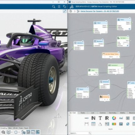
5. CATIA V6 Reverse Engineering Services – Native CATIA V6 Models with Construction History
Our CATIA V6 reverse engineering services deliver fully editable native CATIA V6 CAD models with complete construction history for advanced engineering and product development. We accurately convert scanned components, mesh files, and legacy parts into feature-based parametric models that preserve design intent and enable future modifications. Ideal for aerospace, automotive, industrial equipment, and precision manufacturing, our CATIA V6 reverse engineering solutions provide production-ready CAD data that integrates seamlessly into enterprise PLM workflows.
Key Benefits
- Native CATIA V6 CAD models with feature history
- Fully parametric and editable geometry
- High-precision 3D scan to CAD conversion
- Supports aerospace, automotive, and industrial applications
- Preserves design intent for future engineering changes
- Ready for manufacturing, validation, and PLM integration
Reverse-Engineering in Volume-Data
Create CAD files out of Scan Data
For processing as a complete element in a sequel construction, for measurements or e.g for calculations of volumes, cheaper and faster created Volume-Data is sufficient. We create Volume-Data with Siemens NX or Design X.
- Design X (Geomagic) - The scan-data will be read and converted into surfaces in a mix of manual und semi-automated process.
- SiemensNX - The scan-data will converted into surfaces manually after reading the data.
The resulting data is available in STEP format as a *.stp file.
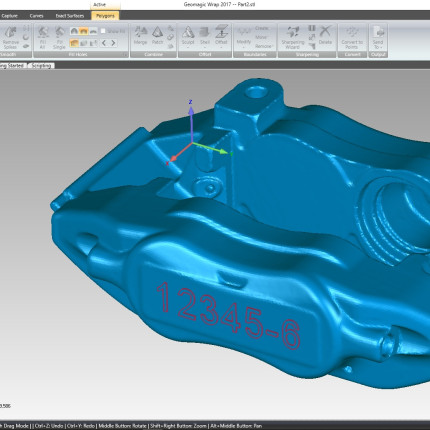
1. DesignX – Reverse-Engineering in STEP
DesignX Reverse Engineering Services – STEP-Based CAD Models
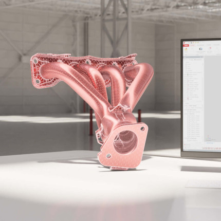
Our DesignX reverse engineering services convert 3D scan data, mesh files (STL, OBJ), point clouds, and physical components into accurate STEP-based CAD models using Geomagic Design X. The reverse engineering workflow combines scan processing, feature extraction, surface reconstruction, and CAD modeling to create editable and manufacturing-ready geometry. STEP output provides broad compatibility with leading CAD platforms, making it suitable for product redesign, engineering analysis, manufacturing, and downstream CAD workflows. Whether you need to digitize legacy components, recreate complex parts, or convert scan data into usable CAD geometry, our DesignX reverse engineering solutions deliver accuracy, flexibility, and cross-platform compatibility.
Key Benefits
- Accurate STEP (.STEP & .STP) CAD output
- Advanced 3D scan-to-CAD conversion using DesignX
- Feature-based and surface-based reverse engineering
- Suitable for complex and freeform components
- Compatible with major CAD platforms and downstream workflows
- Ideal for product redesign, manufacturing, and inspection
- Supports legacy component digitization and engineering modifications
2. DesignX – Reverse-Engineering in IGES
DesignX Reverse Engineering Services – IGES-Based CAD Models
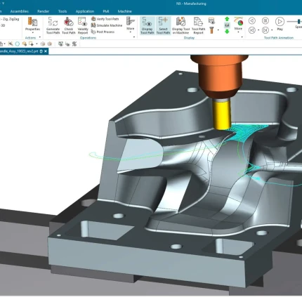
Our DesignX reverse engineering services transform 3D scan data, mesh files (STL, OBJ), point clouds, and physical components into accurate IGES-based CAD geometry using Geomagic Design X. We use advanced scan processing, feature extraction, surface fitting, and reverse engineering techniques to recreate complex components with precision. IGES output enables smooth data exchange across different CAD and engineering environments, making the models suitable for design development, manufacturing, inspection, and engineering applications. Whether you need to digitize legacy parts, recreate discontinued components, or convert scanned geometry into reusable CAD data, our DesignX reverse engineering solutions provide reliable accuracy and flexible interoperability.
Key Benefits
- Accurate IGES (.IGES & .IGS) CAD output
- High-precision 3D scan-to-CAD conversion
- Advanced surface reconstruction and feature extraction
- Supports complex, organic, and freeform geometries
- Easy data exchange across multiple CAD platforms
- Ideal for product redesign, manufacturing, and inspection
- Supports legacy part digitization and engineering modifications
3. Siemens NX – Reverse-Engineering in STEP
Siemens NX Reverse Engineering Services – STEP-Based CAD Models
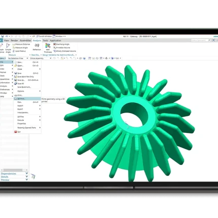
Our Siemens NX reverse engineering services convert 3D scan data, mesh files (STL, OBJ), point clouds, and physical components into accurate STEP-based CAD models using Siemens NX. The process combines scan data processing, surface reconstruction, feature creation, and precise CAD modeling to recreate components for engineering and manufacturing applications. STEP output enables compatibility with a wide range of CAD platforms while preserving accurate geometric information for downstream design and manufacturing workflows. Whether you need legacy component digitization, product redesign, or manufacturing-ready CAD data, our Siemens NX reverse engineering solutions deliver precision, interoperability, and dependable engineering results.
Key Benefits
- Accurate STEP (.STEP & .STP) CAD output
- Precision scan-to-CAD conversion using Siemens NX
- Advanced surface and feature-based modeling
- Supports complex and freeform component geometries
- Compatible with major CAD systems and manufacturing workflows
- Ideal for product redesign, engineering, and manufacturing
- Supports legacy part digitization and design modifications
4. Siemens NX – Reverse-Engineering in IGES
Siemens NX Reverse Engineering Services – IGES-Based CAD Models
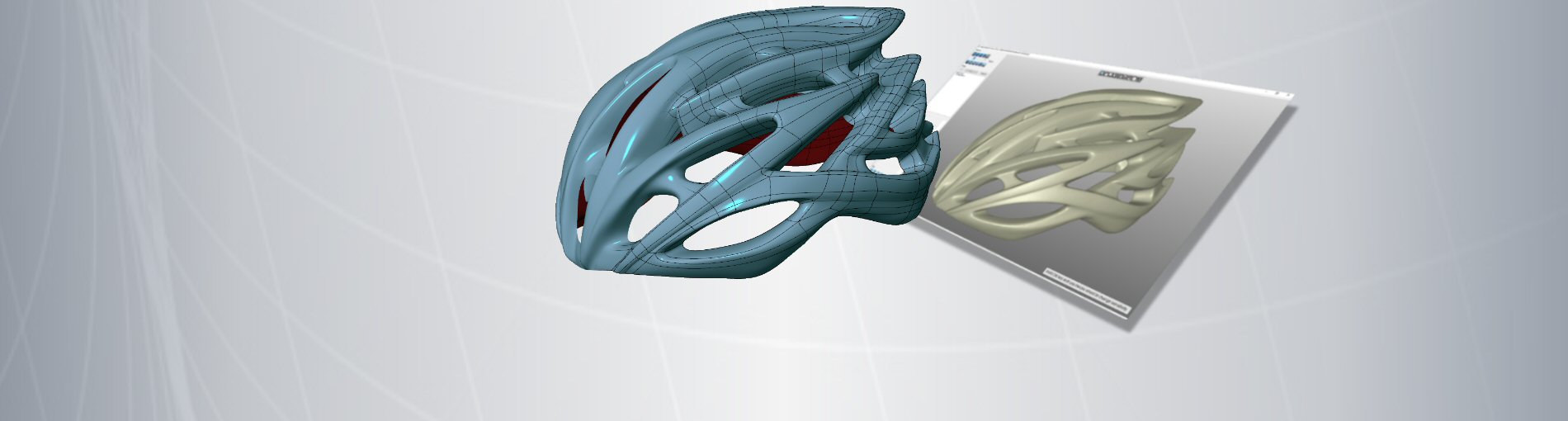
Our Siemens NX reverse engineering services transform 3D scan data, mesh files (STL, OBJ), point clouds, and physical components into accurate IGES-based CAD geometry using Siemens NX. Our engineers apply scan processing, surface reconstruction, feature modeling, and precision CAD techniques to recreate components for a variety of engineering applications. IGES output supports efficient CAD data exchange across different design and manufacturing platforms, making the resulting geometry suitable for product development, redesign, manufacturing, and inspection. Whether you need to recreate legacy components, digitize physical parts, or convert scanned data into reusable CAD geometry, our Siemens NX reverse engineering solutions provide accuracy, interoperability, and flexibility.
Key Benefits
- Accurate IGES (.IGES & .IGS) CAD output
- High-precision scan-to-CAD conversion using Siemens NX
- Advanced surface reconstruction and feature modeling
- Supports complex, organic, and freeform geometries
- Flexible CAD data exchange across multiple platforms
- Ideal for product redesign, manufacturing, and quality inspection
- Supports legacy component digitization and engineering modifications
OUR SERVICE
Reverse Engineering - consulting on 3D technologies
Our TEAM, of currently approx. 30 engineers, processes 3D scan data for import into your CAD software. As a service provider for reverse engineering, we have a network of partners and colleagues who offer almost every service in the 3D area. We assist in creating a 3D scan, data preparation and we can help with 3D printing. For your toolmaking processes, the scanning of a model and converting it into CAD / CAM dataset can provide a significant time and cost advantage. - We are happy to help.
Reverse Engineering - Quality and benefits through digitization
Increase your product quality by creating accurate 3D scans. Your production benefits from optimally prepared data for the tool design. The quick replacement of your component offers new possibilities in communication.
EXPLANATION OF REVERSE ENGINEERING - DO YOU HAVE A QUESTION?
If you submit your contact information here, you will get a link to download the Sample Reverse Engineered data. Take your time to evaluate the quality of our Reverse Engineering or use the 'Message' field to submit a request or question to our team of experts.
PARTNERS
Our cooperation partners...